
 Contact Us

Rapid Prototyping 3D Printing- Methods, Materials, Process and How to Choose


Table of Contents

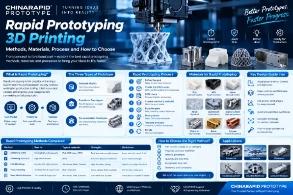
Rapid Prototyping 3D Printing is the practice of turning a CAD model into a physical part quickly, without waiting for production tooling. Instead of spending weeks and a large budget on molds or dies, a team can hold a real part within hours or days, test it, change the design and build the next version. That speed lets teams find problems while changes are still cheap, and it is why prototyping is now part of almost every product development plan.
This guide explains what rapid prototyping is, the three types of prototype, the process step by step, how the main methods compare, and how to choose the right one. If you already have a design, our prototype design team can review it directly.
What Is Rapid Prototyping?
Rapid prototyping is a set of techniques for making a physical model of a part or assembly directly from digital data. The goal is to learn something from the part: how it looks, whether it fits, how it handles load, or whether it can be made in volume. Each prototype answers a question, the answer feeds the next design revision, and the loop repeats until the design is ready for production.
The term began with the first layer-by-layer printing machines in the late 1980s, and for years it was used almost interchangeably with 3D printing. Today the two are not the same:
- 3D printing is a family of manufacturing technologies.
- Rapid prototyping is a purpose: getting a testable part fast. It can use 3D printing, CNC machining, vacuum casting, sheet metal fabrication or a combination.
Many printed parts are no longer prototypes at all, and many prototypes are not printed. Choose the process by what you need to learn, not by which technology is fashionable.
Why Prototype Rapidly?
- Shorter development cycles. Waiting weeks for each sample limits the number of design loops. Getting parts in days allows more iterations in the same schedule.
- Lower risk. Errors found in a prototype cost far less than errors found after tooling is cut.
- Better communication. A physical part gives designers, engineers, buyers and investors the same reference, which removes misunderstandings that drawings and renders leave behind.
- Realistic testing. Fit, assembly, ergonomics, heat, load and appearance are far easier to judge on a real part than on a screen.
- Freedom to experiment. When a revision costs a file change and machine time, teams try more ideas and settle on stronger designs.
- Easier customisation. Digital workflows make it simple to produce variations for different users or markets.
The Three Types of Prototype
Engineers usually classify prototypes by purpose:
- Concept models test form, proportions and overall idea. Speed matters more than material properties, so low-cost materials and rough finish are acceptable.
- Functional prototypes behave like the final part in the ways being tested: stiffness, fit, motion, assembly, sealing, heat. They use materials and processes close enough to the final product to give meaningful results.
- Pre-production prototypes are built with the intended production materials, tolerances and finish. They validate the design and the manufacturing plan before you commit to tooling or volume.
A useful rule: pick the cheapest, fastest method that still answers the question you are asking at that stage.
The Rapid Prototyping Process, Step by Step
- Define the goal. State what this prototype must prove: appearance, fit, function or manufacturability.
- Create the CAD model. Build a 3D model with realistic dimensions, wall thickness, tolerances and features.
- Run a manufacturability check. Review the design for features that will be difficult or costly to make with the chosen process. This is where many problems are cheapest to fix. Our team provides DFM feedback within 24 hours of receiving your files.
- Choose the process and material. Match the method to part size, detail, strength, finish and quantity (see the comparison below).
- Build the part. Printing, machining, casting or fabrication. Lead times range from hours or a few days for simple parts to several days for complex multi-stage builds.
- Post-process. Support removal, deburring, sanding, painting, plating or assembly to bring the part to the required quality.
- Test and evaluate. Check fit, function, strength and appearance against the goals you set in step 1.
- Iterate. Update the model, rebuild and repeat until the design is validated.
Rapid Prototyping Methods Compared
| Method | Best for | Typical materials | Strengths | Limitations |
| FDM / FFF 3D printing | Early concept models, jigs, large simple shapes | Common thermoplastics | Low cost, quick, easy to start | Visible layer lines, lower accuracy |
| SLA (resin) 3D printing | Detailed, smooth, visual models | Photopolymer resins | Fine detail, good surface | Resins can be brittle, needs curing |
| SLS (powder) 3D printing | Functional plastic parts, complex shapes | Nylon and similar powders | No supports, good strength | Grainy surface, powder removal |
| Metal 3D printing (DMLS) | Complex metal parts, internal channels | Steel, aluminium, titanium alloys | Complex geometry in metal | Higher cost, post-processing needed |
| CNC machining | Precise parts in real metal or plastic | Aluminium, steel, brass, titanium, engineering plastics | Tight tolerances, true material properties, good finish | Tool access limits shape, waste |
| Vacuum casting | Small batches of plastic parts that look like production | Polyurethane resins that mimic common plastics | Good surface, soft or rigid options, low tooling | Mould life is limited |
| Sheet metal fabrication | Enclosures, brackets, frames, chassis | Steel, stainless, aluminium, copper | Production-like metal parts, quick turnaround | Needs bend and forming rules |
| Rapid tooling and injection molding | Pre-production and production plastic parts | Production thermoplastics | Final material and process | Tooling cost and lead time |
Learn more on each service page: 3D printing, CNC machining, vacuum casting, sheet metal fabrication and injection molding. Our homepage also lists SLA, SLS and DMLS support under rapid prototyping projects.
How to Choose the Right Prototyping Method
Work through these questions in order:
1. What do you need to learn?
- Shape and proportion: concept model, fastest and cheapest process.
- Fit and function: functional prototype in a similar material.
- Final validation: production-intent material and process.
2. What material does the part need?
If the final part is metal and the test depends on strength, heat or conductivity, use machining or sheet metal rather than a plastic stand-in. If the test is only about shape or fit, a printed model is usually enough.
3. How precise must it be?
Tight tolerances and sealing surfaces point to CNC machining. Looser visual models suit printing.
4. How big and how complex is it?
Thin-walled boxes and brackets suit sheet metal. Complex internal features suit 3D printing. Solid blocks with pockets and bores suit machining.
5. How many do you need?
| Quantity | Typical choice |
| 1–5 | 3D printing, CNC machining or sheet metal |
| 5–50 | Vacuum casting, machining, sheet metal |
| 50–1,000 | Vacuum casting, rapid tooling, low volume production |
| 1,000+ | Injection molding with production tooling |
6. What finish do you need?
A prototype for a trade show or investor needs a production-quality finish, so plan for painting, texturing or anodising. A test part usually does not.
Material Considerations
- Plastics: common options include ABS-like, nylon-like, transparent, flexible and high-temperature grades. Cheap materials are fine for concept work, and engineering plastics are better for functional tests.
- Metals: aluminium for light parts, stainless steel for corrosion resistance, steel for strength, brass and copper for conductivity or appearance.
- Match the final process. If the final part will be injection molded, remember that a prototype made another way will not have identical strength, shrinkage or surface. Treat test results with that in mind.
Browse supported options on our materials page.
Finishing Your Prototype
Appearance often decides whether a prototype can be used for reviews, photography or sales. Typical steps include sanding, bead blasting, painting, powder coating, anodising, plating and texturing. Plan finishing early, because it can change dimensions and fit. See surface finishing and CMF surface finishing.
The Prototype-to-Production Path
A common sequence is:
- Concept model: printed or hand-finished, for form and layout.
- Appearance model: finished surface, colour and texture, for design review.
- Functional prototype: real or similar materials, for fit and performance tests.
- Engineering validation build (EVT): early builds checking the design meets engineering requirements.
- Design validation build (DVT): cosmetics, durability and environment testing.
- Pilot or low-volume run: production-like parts to confirm process and quality.
- Tooling and volume production: once the design is frozen.
Moving through these stages with one partner means your files, materials and quality records carry forward. See our low volume production service for the bridge to full production, and our rapid tooling projects for examples of tooling built after validation.
Common Challenges and How to Avoid Them
| Challenge | How to reduce the risk |
| Prototype material behaves differently from the final one | Use the closest material available and note the differences in test results |
| Design flaws not caught in a fast build | Plan tests in advance and check against a written requirements list |
| Strength or durability not representative | Use machining or sheet metal for load-bearing tests |
| Over-polished prototype hides manufacturing problems | Review the design for production processes as well as appearance |
| Too many iterations without clear goals | Define the question each prototype must answer |
| Tolerance problems at assembly | Check mating features early and allow for finishing thickness |
| Cost creeping up | Match fidelity to the stage: cheap models early, higher quality later |
Design Tips for Prototype Success
- Design for the process. Each method has its own limits on wall thickness, undercuts, tool access and bend radii.
- Keep wall thickness uniform to reduce warping and print failure.
- Add radii to internal corners for machined parts.
- Avoid unnecessary features that add cost without helping the test.
- Split large parts into sections if they exceed the build size, and design clean joints.
- Call out critical tolerances on a drawing, and let the rest use general tolerances.
- Plan for assembly. Allow for clearances, fasteners, inserts and finishing thickness.
- Share a 2D drawing with the 3D model for tolerances, threads and finishes.
For deeper design advice, read our related guides on CNC design for manufacturability and our tolerance and quality control standards.
Applications by Industry
- Consumer electronics: housings, frames and internal structures for fit and look checks. See consumer electronics.
- Home appliances: appearance models and functional builds. See home appliance.
- Automotive: brackets, housings, panels and test fixtures. See automotive.
- Aerospace: lightweight, high-precision parts and test articles. See aerospace.
- Medical devices: precision non-implant components and enclosures. See medical devices.
- Robotics and automation: structural parts, end-effectors, jigs and fixtures. See robotics and automation.
- Industrial equipment: guards, frames and functional assemblies. See industrial equipment.
The Future of Rapid Prototyping
Several trends are shaping how prototypes are made:
- Smarter design tools that suggest geometry and flag problems before a part is built.
- Virtual and augmented reality reviews that let teams check fit and ergonomics before ordering a physical part, reducing the number of builds.
- Larger-format printing that makes full-size parts and fewer assembled pieces practical.
- Production-grade materials in printing and casting, narrowing the gap between a prototype and the final part.
- Hybrid workflows that combine printing, machining and finishing in one project.
None of these remove the need to test a real part. They help teams reach a better design in fewer loops.
FAQ
What is rapid prototyping?
A set of methods for making a physical model of a part quickly from CAD data, so it can be tested and improved before production.
Is rapid prototyping the same as 3D printing?
No. 3D printing is one technology used for prototypes. CNC machining, vacuum casting and sheet metal fabrication are also common.
How fast can I get a prototype?
Simple parts can be ready in days. Our homepage lists rapid prototyping lead times of 3–5 days for complex CNC parts, and global delivery within 3–7 days.
What is the cheapest way to prototype?
Usually 3D printing in a basic plastic for concept models, and sheet metal or CNC machining when you need metal and tolerance.
Can I order a single prototype?
Yes. We support custom parts manufacturing with a minimum order quantity of 1.
How accurate are prototypes?
It depends on the method. Machined parts can hold tight tolerances, while printed and cast parts are generally looser. Check capabilities on our tolerance page before finalising a design.
What files do I need to send for a quote?
A 3D model such as STEP, plus a 2D drawing if you have tolerances, threads or finishes to specify.
When should I move from prototype to production tooling?
When the design has passed testing, dimensions are stable and your volume justifies tooling cost. Many teams bridge the gap with a low-volume run first.
Ready to build your prototype? Send your drawings and 3D models and our engineers will review them for process fit, lead time and cost.
- PREV: Null
- NEXT: Null
Talk to the Manufacturer, Not a Middleman
Resources & Insights
-
Blog
Household Appliance Prototyping Services: From Concept to Market-Ready Products
2026-10-26By -
 Blog
Rapid Prototyping 3D Printing- Methods, Materials, Process and How to Choose
2026-10-23By -
 Blog
Sheet Metal Forming - Processes, Materials, Thickness and Design Guide
2026-10-23By -
 Blog
Low Volume Appliance Manufacturing Methods and Processes
2026-10-23By


