
 Contact Us

CNC Milling Explained - Operations, Tolerances and When to Choose It


Table of Contents

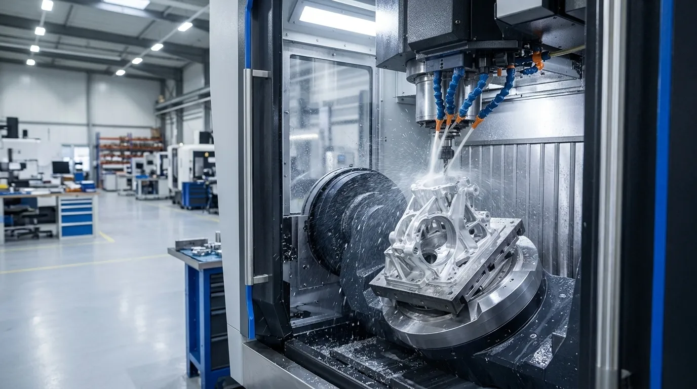
CNC milling is a subtractive process. A rotating cutting tool, guided by a computer program, removes material from a solid block to leave the finished part. It sits behind engine housings, robot arm brackets, aluminium electronics enclosures and surgical-instrument parts. Many of these start as a one-off prototype and later move into batches.
This guide covers how milling works, the main operations, what tolerances to expect, which design features to avoid, and how to decide whether milling is the right process. If you already have a drawing, our CNC machining team can review it directly.
What Is CNC Milling?
CNC stands for computer numerical control. In manual milling an operator steers the tool by hand from a drawing, which is slow and varies from part to part. In CNC milling a program controls the spindle speed, feed rate, toolpath and depth of cut, so the hundredth part matches the first.
CNC milling is one branch of CNC machining. Turning rotates the workpiece against a fixed tool and suits round parts, while milling rotates the tool against a mostly fixed workpiece and suits prismatic, pocketed and contoured parts. Many real parts need both, which is why shops run mills and lathes side by side.
How the CNC Milling Process Works
- CAD model. The designer builds a 3D model with dimensions, tolerances and material. A manufacturability check at this stage prevents most cost surprises.
- CAM programming. CAM software turns the model into G-code: tool selection, toolpaths, speeds, feeds and coolant commands.
- Machine setup. The operator loads tools, clamps the workpiece and sets the work origin.
- Machining. The machine runs the program. Roughing removes bulk material with larger tools, then semi-finishing and finishing passes with smaller tools bring the part to size and surface quality.
- Post-processing. Deburring, bead blasting, anodising, plating or heat treatment, as the application requires.
- Inspection. Critical dimensions are measured against the drawing.
Cutting direction also matters. In climb milling the tool turns with the feed, so the chip starts thick and ends thin. This gives a cleaner surface, longer tool life and less heat going into the part. In conventional milling the tool turns against the feed, which causes more rubbing at the start of each cut. Most modern CNC work uses climb milling where the setup allows it.
Main CNC Milling Operations
| Operation | Tool orientation | Typical output |
|---|---|---|
| Face milling | Tool axis perpendicular to the surface | Flat faces and good surface finish |
| Plain (peripheral) milling | Tool axis parallel to the surface | Slots, pockets, walls and steps |
| Angular milling | Tool tilted or angled cutter | Chamfers, dovetails, angled grooves |
| Form milling | Shaped cutter matching the profile | Curves, radii, grooves and contours in one pass |
| Profile milling | Roughing, semi-finishing and finishing passes | Convex and concave outlines and 3D surfaces |
| Gang milling | Several cutters on one arbor | Repeated patterns in fewer passes |
| Slot and side milling | Cutter narrower than the part | Slots and vertical flat walls |
Drilling, tapping, boring and thread milling are also done on the same machine, so a finished part often needs a single setup.
How Many Axes Do You Need?
- 3-axis: the tool moves in X, Y and Z. It is the workhorse for flat, pocketed and prismatic parts, and it is usually the cheapest per hour.
- 3+2 (positional 5-axis): the part is tilted to a fixed angle, then cut in three axes. It reaches angled features without multiple manual setups.
- 4-axis: adds rotation around the X-axis, so you can machine several sides without re-clamping.
- 5-axis: adds a second rotation. It cuts complex surfaces such as impellers, turbine blades and organic housings in one clamping, which improves accuracy between features and often shortens the total job.
A rule of thumb: choose 3-axis if every feature can be reached from the top, and move to 4- or 5-axis when features sit on several faces, at compound angles, or when tight relationships between faces matter. For more on multi-axis work, see our article on industry-leading 5-axis CNC machining solutions.
Machine Types
- Vertical mills have a vertical spindle, give good visibility, and are cheaper and more widely available. They suit most prototype work.
- Horizontal mills have a horizontal spindle. Chips fall away from the cut, which helps finish and tool life, and they suit heavy or high-volume work.
- Bed-type and planer-type mills carry larger, heavier workpieces and several tools.
- Knee-type mills are common for small, one-off or maintenance parts.
CNC Milling Tolerances
Milling is one of the more precise ways to make a metal part, but a tolerance is never free. Published shop standards generally quote about ±0.005 in (±0.13 mm) for standard work, with tighter results of ±0.001 in (±0.025 mm) or better possible on selected features with the right machine, tooling and inspection. A few things to keep in mind:
- Tolerance drives cost. Each step tighter adds machining time, slower finishing passes, more inspection and sometimes a different machine.
- Tolerance only where needed. Apply tight limits to mating surfaces, bearing bores and datum features, and leave everything else on a general tolerance.
- Material and size matter. Aluminium holds tight limits easily. Plastics move with temperature and clamping force. Long, thin parts bow.
- Surface finish is separate. As-milled finish is typically visible tool marks, and tighter finish requires extra passes or post-processing.
- Standards: ISO 2768 and ISO 286 are the common references for general and fit tolerances.
Yanmee’s homepage lists ±0.01 mm precision builds for CNC machining. See the Tolerance and Quality Control page for what is held on which features and how parts are inspected.
Design Guidelines for CNC Milled Parts
- Add radii to internal corners. Cutters are round, so sharp internal corners cannot be machined. Use a radius slightly larger than the cutter radius.
- Avoid deep, narrow pockets. Keep depth to a few times the cutter diameter, because long tools deflect and chatter.
- Keep walls from getting too thin or too tall. They vibrate and can distort during cutting.
- Avoid undercuts and curved holes unless the geometry justifies special tools or a multi-axis setup.
- Design features the tool can reach. If the cutter cannot get to a face, the feature cannot be milled.
- Do not model threads. Specify them in the drawing, and let the shop tap or thread-mill them.
- Standardise hole sizes and radii so fewer tool changes are needed.
- Call out only critical dimensions and tolerances on the drawing. Use a 2D drawing alongside the 3D file for threads, tolerances and finishes.
Our article on CNC design for manufacturability: 10 mistakes to avoid before production goes deeper on all of these.
Materials for CNC Milling
- Metals: aluminium (6061, 7075), stainless steel (303, 304, 316), mild and alloy steel, tool steel, brass, copper and titanium.
- Plastics: ABS, nylon, polycarbonate, POM (acetal), PMMA, PTFE and PEEK.
Choose by working environment, strength, weight, corrosion resistance, finish options and cost. Machinability also matters: aluminium and brass cut fast, stainless and titanium cut slowly and wear tools faster. Browse the full list on our materials page.
Finishing Options
Parts come off the machine with tool marks. Common finishes include bead blasting, anodising (Type II or III for aluminium), powder coating, polishing, brushing and passivation for stainless steel. Finishing can change dimensions slightly, so account for it on tight fits. See surface finishing and our CMF surface finishing service for the options.
What Affects CNC Milling Cost?
- Design complexity: more features, tighter tolerances and more setups mean more machine time.
- Machine type: 3-axis time costs less than 4- or 5-axis time, but 5-axis can cut the number of setups.
- Material: raw stock price plus how fast it machines.
- Quantity: setup and programming cost spreads across more parts as volume grows.
- Finishing and inspection: anodising, plating and full inspection reports add cost.
- Lead time: rush orders cost more.
When to Choose CNC Milling (and When Not To)
| Choose CNC milling when… | Consider something else when… |
|---|---|
| You need metal parts with tight tolerances | The part is an enclosure with uniform wall thickness (sheet metal is cheaper) |
| You need functional prototypes in production materials | You need lots of complex plastic parts (injection molding wins at volume) |
| Parts are small to medium and 3D (pockets, bores, threads) | You need internal channels or lattices that tools cannot reach (3D printing) |
| You need repeatability from one to a few thousand parts | You need a quick visual model (3D printing or vacuum casting) |
| Surface finish and flatness matter | Material waste on a large block is a concern |
Compared with the main alternatives:
- vs 3D printing: milling gives better tolerances, finish and material properties and handles threaded holes well. Printing wins for undercuts, internal features and organic shapes. See 3D printing.
- vs sheet metal: sheet metal is cheaper for thin, bent, uniform-thickness parts. Milling wins on thick, solid or highly detailed geometry. See sheet metal fabrication.
- vs injection molding: molding has high tooling cost but very low per-part cost at volume. Milling avoids tooling and suits early-stage and low-volume work. See injection molding.
- vs vacuum casting: casting gives small batches of plastic parts from a master. See vacuum casting.
A common path is prototype by milling or printing, validate, then move to low volume production or tooling once the design is frozen.
Advantages and Limitations
Advantages
- High accuracy and repeatability
- Wide material range, from aluminium to titanium to engineering plastics
- No tooling cost, so a single part is practical
- Good surface finish and the ability to add threads, pockets and fine details in one machine
Limitations
- Subtractive, so there is material waste
- Tool access limits geometry (no sharp internal corners, no curved holes)
- Per-part time stays high for large batches
- Complex parts need multi-axis machines and skilled programming
Applications
- Aerospace: lightweight structural parts, housings and impellers. See aerospace.
- Automotive: brackets, housings, battery and motor components. See automotive.
- Medical: precision non-implant components and instruments. See medical devices.
- Consumer electronics: aluminium frames and housings. See consumer electronics.
- Robotics and automation: structural parts, end-effector components, fixtures and brackets. See robotics and automation.
- Industrial equipment: wear-resistant parts and functional assemblies. See industrial equipment.
To see finished work, browse our CNC machining projects.
FAQ
What is the difference between CNC milling and CNC turning?
Milling spins the tool and suits prismatic parts. Turning spins the workpiece and suits cylindrical parts.
How accurate is CNC milling?
Standard shop tolerance is about ±0.13 mm (±0.005 in). Selected features can reach ±0.025 mm or tighter with the right setup, at higher cost.
Is 5-axis milling always better?
No. It is better for complex or multi-face parts, but 3-axis is cheaper and sufficient for simpler geometry.
What file should I send for a quote?
A 3D STEP file, plus a 2D drawing for tolerances, threads and finishes.
Can I order a single part?
Yes. Yanmee’s homepage lists custom parts manufacturing with MOQ 1.
Ready to quote a part? Contact our engineering team with your drawings and 3D models.
- PREV: Null
- NEXT: Null
Talk to the Manufacturer, Not a Middleman
Resources & Insights
-
Blog
Household Appliance Prototyping Services: From Concept to Market-Ready Products
2026-10-26By -
 Blog
Rapid Prototyping 3D Printing- Methods, Materials, Process and How to Choose
2026-10-23By -
 Blog
Sheet Metal Forming - Processes, Materials, Thickness and Design Guide
2026-10-23By -
 Blog
Low Volume Appliance Manufacturing Methods and Processes
2026-10-23By


